

5G, the Internet of Things (IoT), and growing video-based data transport place heavy pressure on carriers and data centers to upgrade their network capacity to support these data-intensive applications. In addition, recent behavioral changes brought on by the COVID-19 pandemic such as remote working, remote learning, and increased streaming for entertainment will continue well after this health crisis ends. As the explosion in the capacity demands of data-hungry applications outpaces current high-speed transport abilities, 400G is a promising new technology that supports an immediate need in fiber optics with comparatively low operational expenses (OPEX) and a smaller footprint.
400G QSFP-DD Based on PAM4 Modulation
PAM4 is the main modulation b of 400G QSFP-DD, and there are two types:multi-mode and single-mode. The 400G QSFP-DD based on PAM4 modulation uses 8x50G PAM4 modulation on the electrical port side, and 8x50G PAM4 and 4x100G PAM4 modulation types on the optical port side.

Figure1: 400G QSFP-DD based on PAM4 modulation
Multi-mode 400G QSFP-DD
400G multi-mode QSFP-DD has SR8 and SR4.2 interfaces, both of which use 8x50G PAM4 modulation.
SR8: “SR” refers to the use of multimode fiber to transmit a distance of 100m, and “8” indicates that there are 8 optical channels. A total of 16 fibers (8 Tx and 8 Rx) are required for each optical channel operating at 50G PAM4. The SR8 module uses MPO-16 connectors or MPO-24 connectors to connect 8 pairs of fibers.

Figure2: MPO-16 connector and MPO-24 connector
SR4.2: “SR” refers to the use of multimode fiber to transmit a distance of 100m, “4” indicates that there are four optical channels, and “2” indicates that each channel uses two wavelengths. Each optical channel operates at 2x50G PAM4, requiring a total of 8 fibers, and the wavelengths are bidirectional and multiplexed. SR4.2 modules use MPO-12 connectors, and the main advantage of SR4.2 is that it can continue to use existing installed fiber resources.

Figure3: MPO-12 BiDi
Each fiber of SR4.2 in the MPO-12 connector carries 2x50G bidirectional PAM4 signals. SR4.2 also supports MDC and SN connector interfaces.
Table1: 400G mluti-mode QSFP-DD
Single-mode 400G QSFP-DD
Single-mode 400G QSFP-DD can be divided into two groups. One group of optical ports is modulated with 8x50G PAM4, and the other group is modulated with 4x100G PAM4. Both bs use the DSP as a CDR (no analog CDR is built) or use a combination of Gearbox and CDR. The difference is the signaling rate on the line side and the number of lasers used.

Figure4: Two groups of single-mode 400G QSFP-DD
Single-mode QSFP-DD Based on 8×50G PAM4
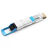
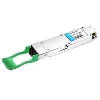
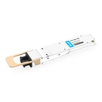
There are three general types: FR8, LR8, and 2xFR4. FR8 and LR8 are the earliest available 400G single-mode interfaces. “8” means 8 wavelengths, and each runs at 50G PAM4. “FR” means 2km transmission, and “LR” means 10km transmission. 8 wavelengths are multiplexed into one fiber. FR8 and LR8QSFP-DD use duplex LC optical interfaces.

Figure 5: Single-mode QSFP-DD based on 8×50G PAM4
The 2xFR4 QSFP-DD uses 8 lasers, but in two groups of 4 wavelengths (following the 200G FR4 standard). The two sets are multiplexed into the fiber separaby, and the QSFP-DD provides 2x200G signals on 2 CS connectors.
Table2: single-mode optical transceiver based on 8×50G PAM4
However, there are trade-offs when using an 8x50G solution. On the one hand, they offer improved b budgets in some cases, but on the other hand, the total laser costs per module are higher and the optical packaging is more complex, resulting in lower yields and higher production costs. In contrast, 4x100G modules have lower power consumption and simpler thermal processing capabilities, so devices are gradually shifting to 4x100G solutions.
Single-mode Optical Module Based on 4x100G PAM4
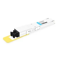
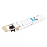
4x100G QSFP-DD optical modules are the current market focus, and the most common part is the use of 4 lanes with 100G PAM4 on the line side. Here, we can classify optical modules into two types: multi-fiber and dual-fiber. The key elements in these optical modules are Gearbox-enabled DSPs, including DR4, FR4, and LR4.
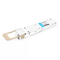
In the DR4 optical module, the DSP converts the 8x50G PAM4 electrical signal to 4x100G PAM4 and transmits it to the optical engine. At the same time, the DSP acts as a CDR. In DR4, each channel operates at 1310nm and requires one fiber, so a total of 8 fibers are required.

Figure6: Single-mode optical module based on 4x100G PAM4
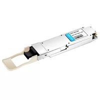
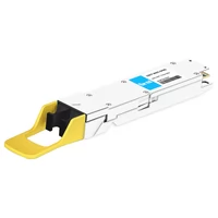
The basic functions of FR4 and LR4 DSPs are the same as those in DR4. But now 4 wavelengths (CWDM4) are used instead of four 1310nm signals and a multiplexer is added to combine these CWDM signals. In this way, the number of optical fibers required is reduced to 2 (TX+RX), and a duplex LC optical port is used.

Figure7: Single-mode 4x100G FR4
For LR4, there are two different routes, and we will most likely end up with two versions. One for 6km (IEEE) and one for 10km (100G lambda MSA).
Table3: Single-mode optical module based on 4×100G PAM4
In the future, considering the costs, 400G transmission with 4-way optical signals may become mainstream. At the same time, the electrical port of the optical module may also be gradually upgraded to the b of 4×100G PAM4 to save the Gearbox chip and save power consumption and cost.
QSFP-DD vs QSFP (QSFP+/QSFP28)
The new QSFP-DD interface expands on the QSFP plugga
The NVIDIA MFP7E30-Nxxx, MPO-12/APC-to-MPO12/APC (8 fibers) passive optical single-mode cable, is designed for bing InfiniBand and Ethernet multimode twin-port OSFP and single-port OSFP and QSFP112 transceivers together.
The Multiple Push On, 12 fiber, Angled Polished Connectors (MPO-12/APC) uses 8 active fibers to transmit light and 4 inactive fibers as strength members. The Angled Polished Connector has a 8-degree polished angle to deflect internal optical back reflections from entering the transceivers and distorting the signal quality.
Twin-port OSFP 800Gb/s transceivers support two, 4-channel fibers which are bed to other twin-port OSFP, single-port OSFP or QSFP112 400Gb/s transceivers.
The fibers are “crossover”, Type-B cables, which enables directly attaching two transceivers together and allow the transmit laser fiber on pin 1 to “crosses over” and align with pin 12 of the opposite fiber end transceiver photodetector.
A typical usecase is bing twin-port OSFP switches to each other, and to ConnectX-7® network adapters and/or BlueField-3® Data Processing Units (DPUs) in compute and storage servers.
Rigorous cable production testing ensures best out-of-the-box installation experience, perbance, and durability. Mellanox optical solutions provide short, medium, and long reach scalability for all topologies, utilizing innovative optical technologies to enable high signal integrity and reliability.
Images are for illustration purposes only. Product labels, colors, and lengths may vary.
Flexible round outer jacket for easier installation
Push-pull latching for quick release
Female-to-Female connectors
9/125 µm Single-Mode fibers
150m max reach
Telcordia GR-1435 compliant
IEC Standard Connectors:
MPO: IEC 61754-7 and ANSI/TIA/EIA 604-5-199
OFNR/LSZH (low smoke zero halogen) jacket
Supports InfiniBand, Ethernet and NVLink protocols
Introduction

Key Features
The system port densities are identical between QSFP-DD and QSFP28 module specifications. However, since each QSFP-DD port can accommodate 8 lanes instead of 4, QSFP-DD doubles the number of ASIC ports it supports for existing interfaces such as CAUI-4. QSPF-DD provides the highest BW density of any pluggable module.
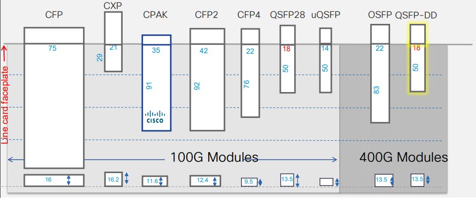
The BW density of QSFP-DD
Systems designed with QSFP-DD modules are backward compatible, allowing them to support existing QSFP modules and provide flexibility for end users and system designers. Backward compatibility is critically important to the industry. The economy of scale achieved due to backward compatibility makes it highly desirable.
In summary, 400G QSFP-DD is a little longer than QSFP+/QSFP28 but the port density is the same, and the bandb is increased to 10 times or 4 times the latter, and it is backward compatible, which means customers can skip the QSFP system and directly deploys the QSFP-DD system, which greatly reduces the equipment costs.
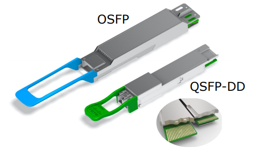
QSFP-DD vs OSFP
First, let’s take a look at OSFP transceiver. The 400G OSFP is a new pluggable b factor with eight high-speed electrical lanes that will initially support 400Gb/s (8x50G). It is slightly wider and deeper than the QSFP but it still supports 36 OSFP ports per 1U front panel, enabling 14.4Tb/s per 1U. Actually, there is not much difference between these two b factors. For example, let’s compare QSFP-DD DR4 with OSFP DR4. The OSFP DR4 is a 400Gb/s Octal Small Form-factor Pluggable (OSFP) optical module designed for 500m optical communication applications. The module incorporates 4 parallel channels on 1310nm center wavelength, operating at 100G per channel. The transmitter path incorporates a quad-channel EML driver together with 4 parallel EMLs. While the QSFP-DD DR4 also supports a max transmission distance of 500 meters on 1310nm center wavelength. But the different part is that the QSFP-DD DR4 module converts 8 channels of 50Gb/s (PAM4) electrical signal into 4 channels of parallel optical output data, each capable of 100Gb/s data rate for an aggregated bandb of 400Gbls.
Second, about the thermal capacity and power consumption. The QSFP-DD is smaller in size, so its thermal capacity is only 7 to 12 watts. While the OSFP transceiver is larger in size, its thermal capacity can reach 12 to 15 watts. The larger the thermal capacity, the greater the power consumption that the optical module can withstand.
Thirdly, the 400G OSFP’s larger size, integrated heatsink, and single-row contacts were initially considered better. Signal integrity through the connector and thermal cooling challenges were prime focus areas. However, QSFP-DD’s backward compatibility to lower speed QSFP28 proved to be a market success once technical concerns were allayed.
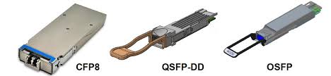
QSFP-DD vs CFP8
The CFP series started from CFP, went to CFP2, then to CFP4, and finally to CFP8, which is also a long-established b-factor series. Compared to the QSFP series, the CFP series seems to have been less popular, for obvious reasons — large size and high power consumption.
Compare QSFP-DD and CFP8, the first obvious thing is the size — the size of CFP8 (41.5mm*107.5mm*9.5mm) is significantly larger than QSFP-DD, and the volume is more than three times that of QSFP-DD.
Besides, for backward compatibility, there is not any mention of backward compatibility in the hardware specification of CFP8 (in fact, the entire CFP series does not seem to be backward compatible). For CFP and CFP2 series optical modules, the CFP to QSFP28 adapter and CFP2 to QSFP28 adapter have been available for a long time, indicating that some users have switched to QSFP28 optical modules.
Then the maximum bandb of CFP8 and QSFP-DD is 400Gb/s, but CFP8 only supports 400Gb/s (16x25G or 8x50G), while QSFP-DD supports both 200Gb/s (8x25G) and 400Gb/s (8x50G). In summary, QSFP-DD seems to be a better choice than CFP8, regardless of any aspect.
QSFP-DD vs QSFP56
As an evolution of the previous 40G QSFP+ and 100G QSFP28, Quad 50 Gigabits Small Form-factor Pluggable (QSFP56) is the one designed for 200G Ethernet. QSFP56 denotes 4 x 50 to 56Gb/s in a QSFP b factor. Sometimes it can also be referred to as 200G QSFP for sake of simplicity. QSFP56 optical modules are similar to QSFP ones in terms of size and b factor. Generally, two QSFP56 modules can be used with an SMF or MMF to realize a 200G b.
The latest iteration of the optical module b factor is from QSFP56 to QSFP56-DD, which is also called 400G QSFP-DD. Though QSFP56-DD has a double density, its size is similar to QSFP56. 400G QSFP56-DD port is backward compatible with the QSFP transceiver which means as long as the switch supports, QSFP56 can work on the QSFP56-DD port. When using a QSFP56 module in a QSFP56-DD port, this port will be configured for a data rate of 200G, instead of 400G.
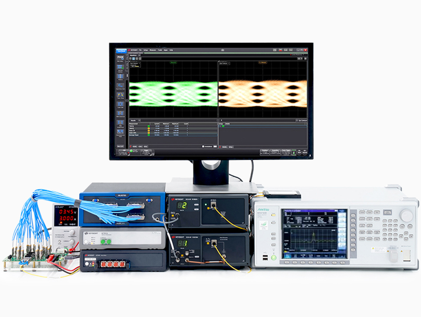
400GbE’s Implementation Challenges
Higher speeds and the utilization of PAM4 modulation do bring great improvements in throughput but also result in high complexity at the physical layer, and it causes signal transmission errors easily.
The first problem is, the higher lane speed in 400G electrical interfaces means more noise (also called signal-to-noise ratio) in signal transmission. And the high signal-to-noise ratio causes an increased bit error rate (BER), which in turn affects the signal quality.
Furthermore, on the physical appearance layer, for 400G optical modules, its high-speed interfaces include more electrical b interfaces, electrical output interfaces, optical b interfaces, optical output interfaces, and other power and low-speed management interfaces. All the perbance of these interfaces should be made to a complaint of 400G standards. However, the size of the 400G transceivers is similar to the existing 100G transceivers, the integration of those interfaces needs more sophisticated manufacturing technology, as well as corresponding perbance tests to ensure the quality of those modules.
At the same time, the complex of the 400G transceiver test also brings new challenges for the optical module vendors. To ensure the transceiver quality for users, vendors have to attach great importance to the transceiver test equipment and R&D technical. How to make sure the new products support the 400G upgrade while dampening associated development and manufacturing test costs that can hamper competitive pricing models, is what they should deal with.
Related Products:
-
 QSFP-DD-400G-SR8 400G QSFP-DD SR8 PAM4 850nm 100m MTP/MPO OM3 FEC Optical Transceiver Module$180.00
-
 QSFP-DD-400G-DR4 400G QSFP-DD DR4 PAM4 1310nm 500m MTP/MPO SMF FEC Optical Transceiver Module$450.00
-
 QSFP-DD-400G-LR4 400G QSFP-DD LR4 PAM4 CWDM4 10km LC SMF FEC Optical Transceiver Module$650.00
-
 QSFP-DD-400G-XDR4 400G QSFP-DD XDR4 PAM4 1310nm 2km MTP/MPO-12 SMF FEC Optical Transceiver Module$650.00
-
 OSFP-400G-SR8 400G SR8 OSFP PAM4 850nm MTP/MPO-16 100m OM3 MMF FEC Optical Transceiver Module$480.00
-
 OSFP-400G-FR4 400G FR4 OSFP PAM4 CWDM4 2km LC SMF FEC Optical Transceiver Module$900.00
-
 NVIDIA MMS4X00-NM-FLT Compatible 800G Twin-port OSFP 2x400G Flat Top PAM4 1310nm 500m DOM Dual MTP/MPO-12 SMF Optical Transceiver Module$1500.00
-
 NVIDIA MMA4Z00-NS Compatible 800Gb/s Twin-port OSFP 2x400G SR8 PAM4 850nm 100m DOM Dual MPO-12 MMF Optical Transceiver Module$750.00
-
 NVIDIA MMA4Z00-NS-FLT Compatible 800Gb/s Twin-port OSFP 2x400G SR8 PAM4 850nm 100m DOM Dual MPO-12 MMF Optical Transceiver Module$850.00
-
 NVIDIA MMS4X00-NM Compatible 800Gb/s Twin-port OSFP 2x400G PAM4 1310nm 500m DOM Dual MTP/MPO-12 SMF Optical Transceiver Module$1500.00
-
 NVIDIA MMA4Z00-NS400 Compatible 400G OSFP SR4 Flat Top PAM4 850nm 30m on OM3/50m on OM4 MTP/MPO-12 Multimode FEC Optical Transceiver Module$900.00
-
 NVIDIA MMS4X00-NS400 Compatible 400G OSFP DR4 Flat Top PAM4 1310nm MTP/MPO-12 500m SMF FEC Optical Transceiver Module$1350.00

